Mobile Robotic Platform Design and Implementation for Simultaneous Localization and Mapping (SLAM)
Github Link for this project
This project was my bachelor capstone project. We were asked to design and implement a mobile robot to create the map of an unknown indoor environment.
Keywords about the project:
- Custom made cost-effective LIDAR
- Communication with ROS
- Simultaneous Localization and Mapping (SLAM)
- Robot Operating System
- Navigation Stack (Autonomous Navigation)
- Hector SLAM, Cartographer SLAM, Gmapping, Karto SLAM, Lago SLAM, Core SLAM
- ROS Serial
- Frontier Exploration
- Gazebo
- CAD Design (Solidworks)
- OpenCV
- PID Controllers
- Embedded Programming (ARM Cortex M10 & STM microprocessors)
- PCB Design
- 3D Printing
We got the following awards with this project:
- Second Best Research Project
- University Students Research Projects Competition
- The Scientific and Technological Research Council of Turkey (TUBITAK)
- Advanced Hardware Design Award
- METU EEE Capstone Project Fair
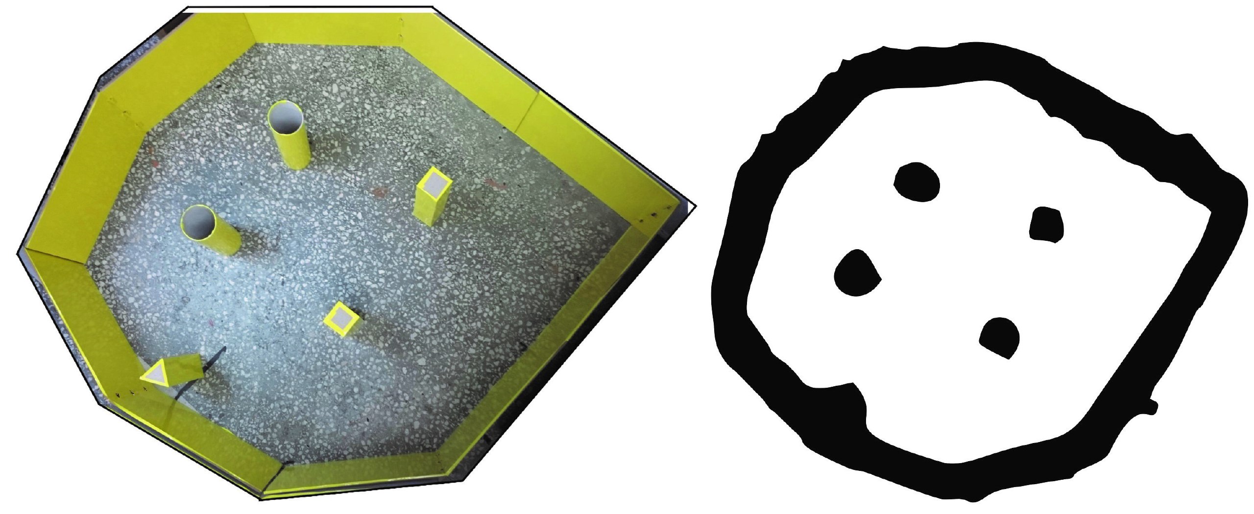
Here is a mapping result after robot autonomosly navigated in an unknown area:
Here is a video of the robot in action:
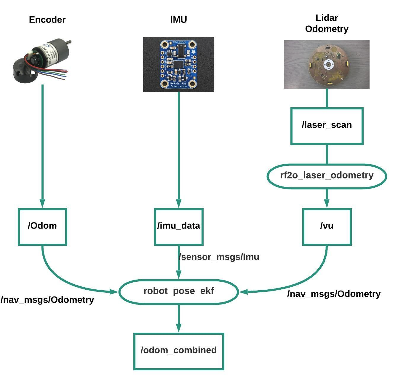
Overall Block Diagram
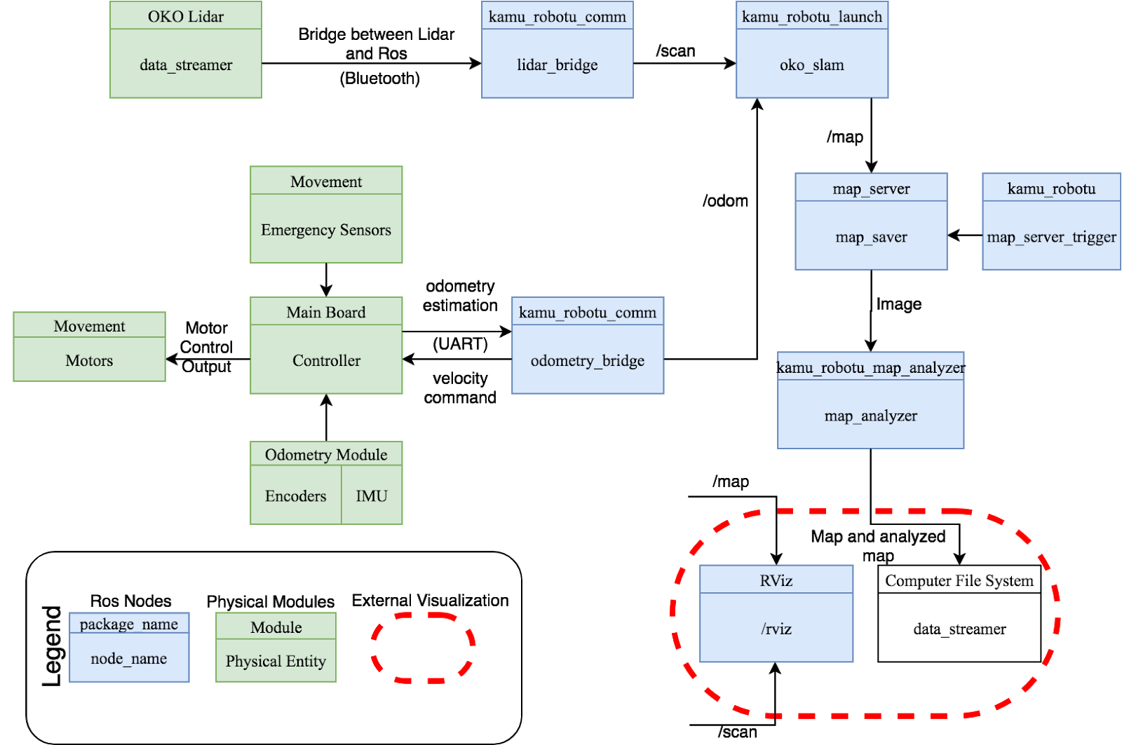
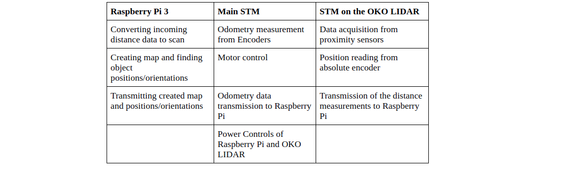
Green filled blocks represents physical blocks while blue filled blocks represents ROS packages/nodes. Connection labels describes the data content that is transferred. Three microcontrollers are used synchronously in this project:
Mechanical Design
In the Solidworks environment, the robot was designed from scratch. A proper environment with real world dimensions were also created in the same way.
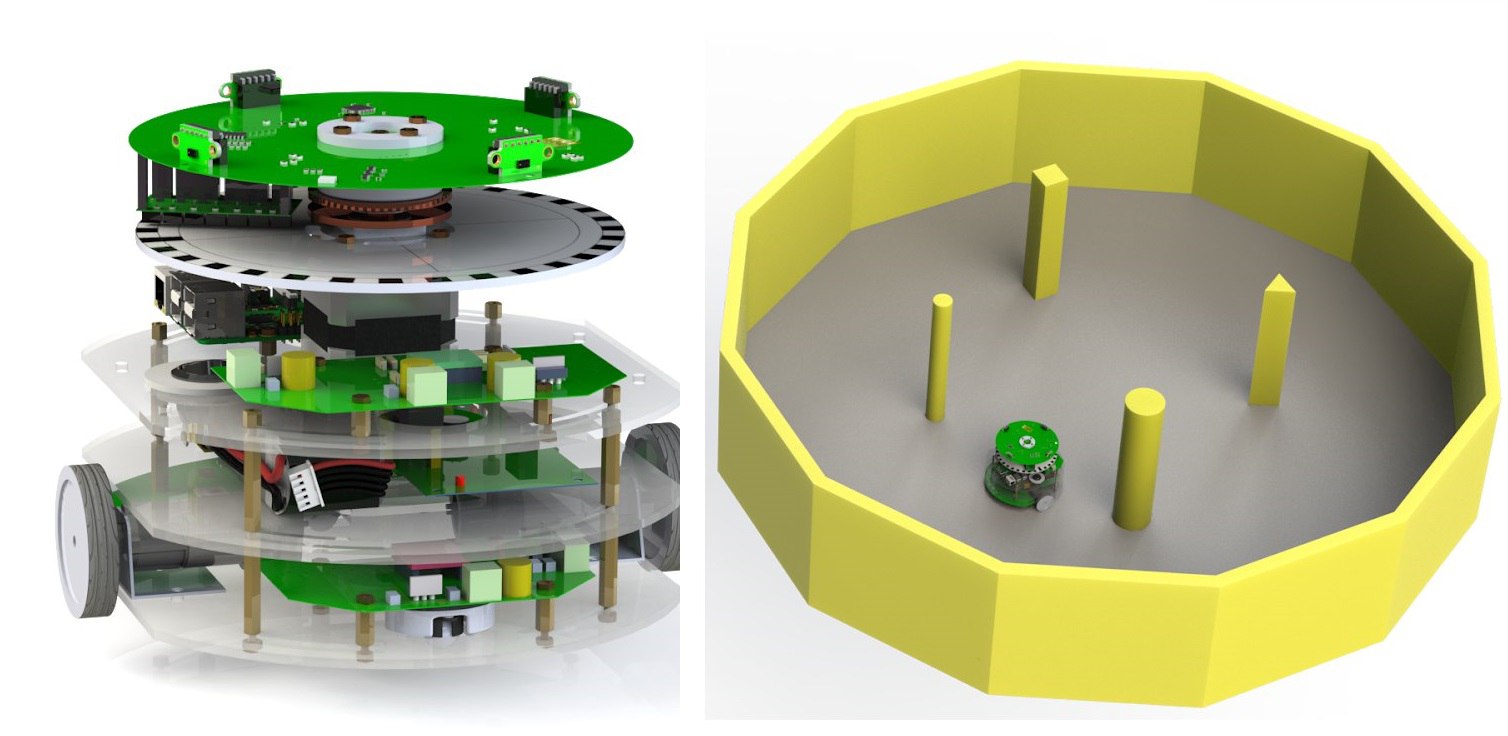
In the end, everything was rendered and these mechanical designs were transferred to ROS environment to test mapping performance in Gazebo simulator.
 .
.
SLAM performance was tested in Gazebo with our custom made LIDAR parameters. For example, a LIDAR with a frequency 2hz and 64 samples per rotation yielded the following mapping:
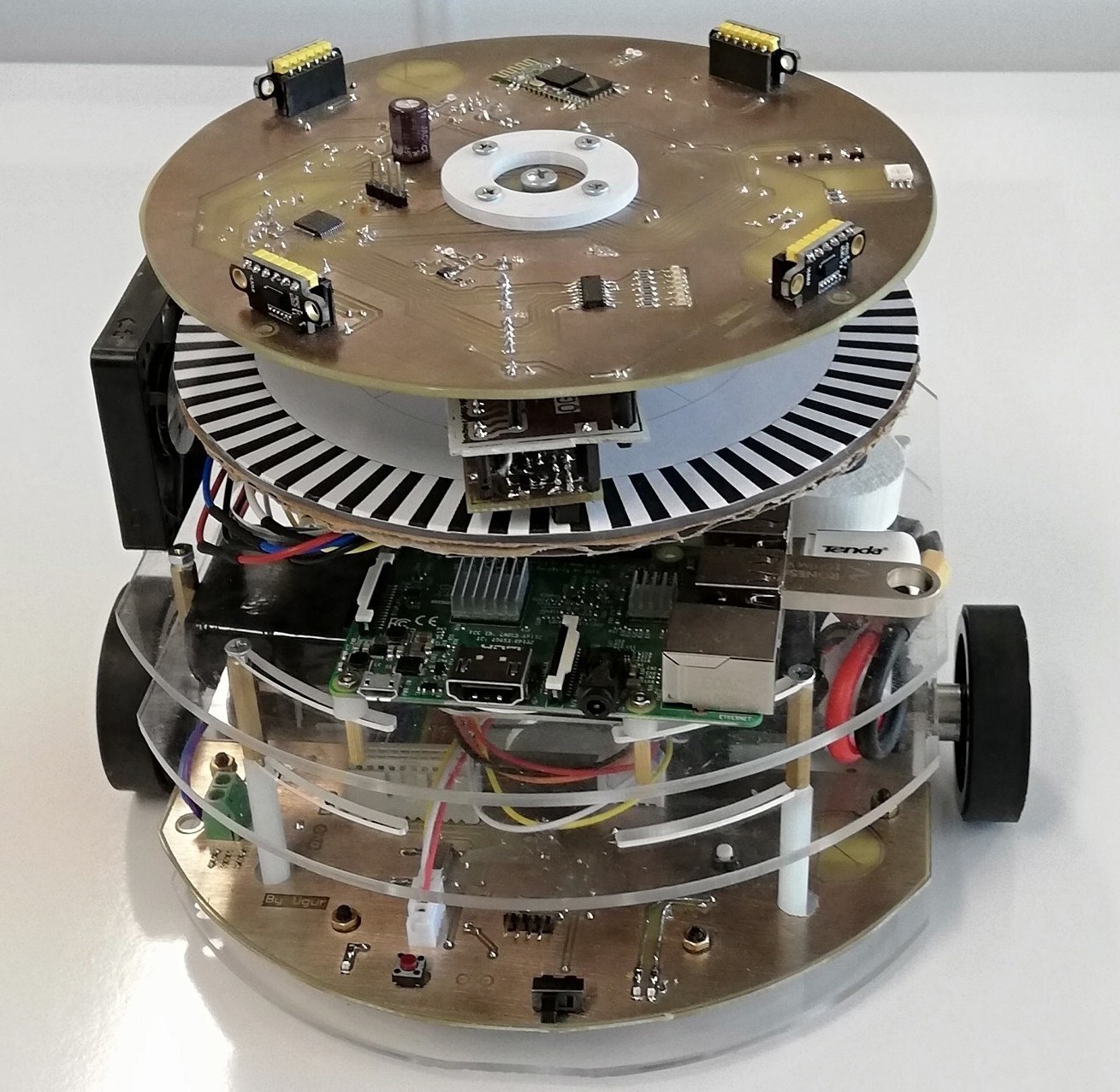
Custom-made LIDAR
The LIDAR collects information about the environment by using 4 x VL53L0X Time of Flight (ToF) sensors and it sends measured data via bluetooth connection. A Nema 17 stepper motor with 1.8 angle resolution (42SHD0001) is used to rotate LIDAR unit. To be able to measure the angle of the lidar with respect to robot, we used optical encoder with 128 point incremental pattern and 1 point index pattern. We are using wireless power to run the LIDAR.
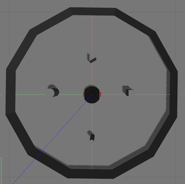
Here is an expansion of LIDAR design in solidworks:
Optical encoder design tests & PCB electrical tests:
LIDAR in action and data transfer to ROS:
Localization
Locazation of the robot was achieved using two encoders on Namiki 22CL-3501PG 12V DC Motors, laser scan data from LIDAR and IMU data. These sensors were read on main STM Controller and they were combined in ROS environment using Extended Kalman Filter (EKF).
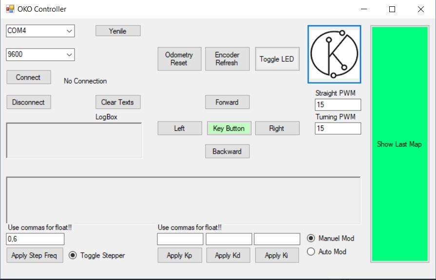
Graphical User Interface (GUI)
A GUI was designed to operate robot easily.
- Connects the robot via bluetooth
- Different modes:
- Autonomous navigation
- Manual, i.e. teleoperation
- Change LIDAR or odometry parameters
- Shows extracted map
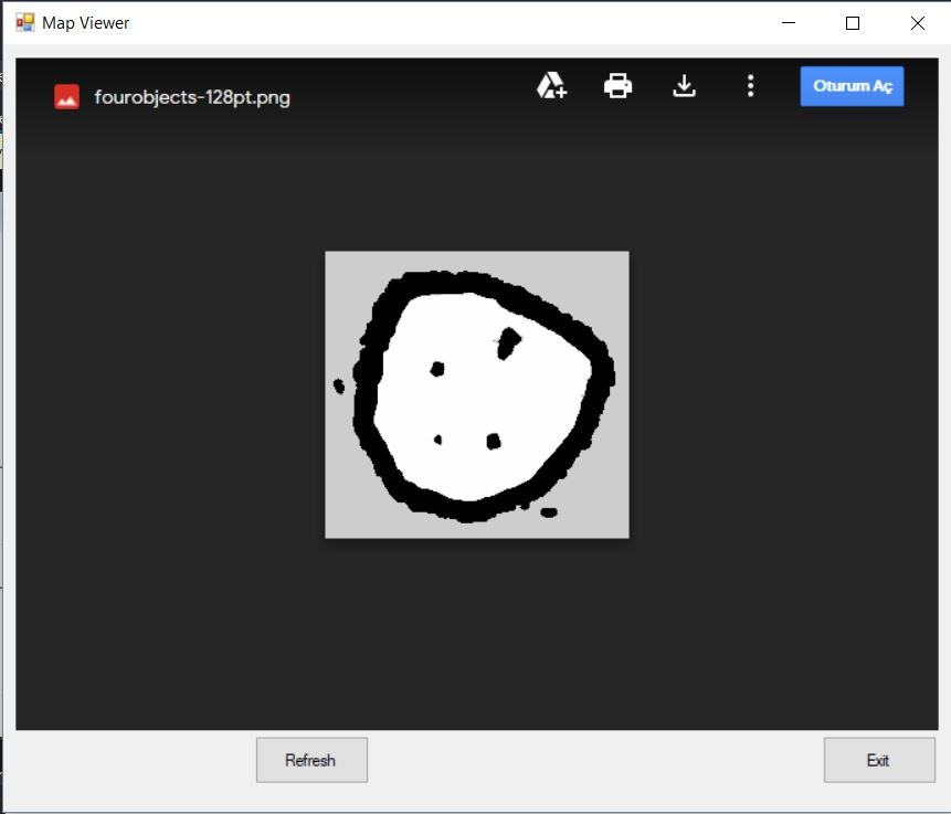
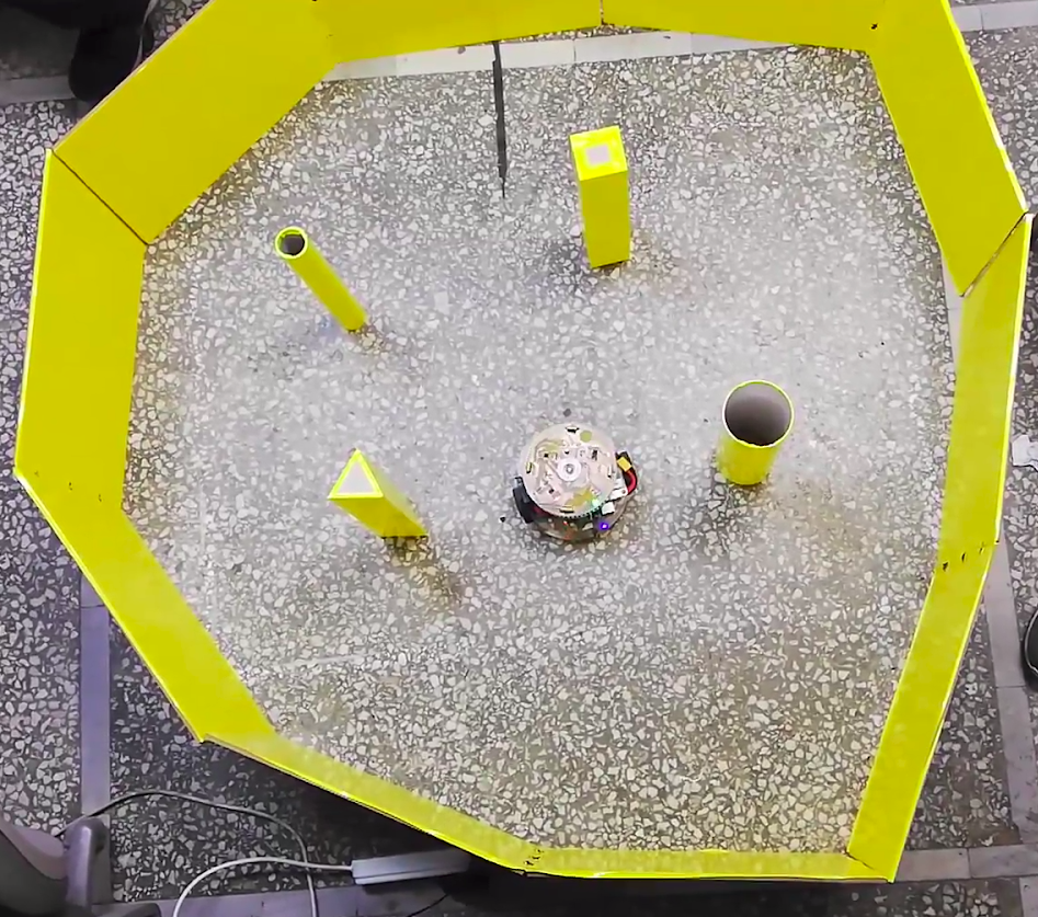
Results
In the end, the robot was tested in real life where it can both autonomously navigate (explore) and extract the mapping of the environment (SLAM) at the same time.
Various SLAM techniques and autonomous navigation algorithms (exploration) were tested such as
- Hector SLAM
- Gmapping
- KartoSLAM
- CoreSLAM
- LagoSLAM
- Explore-LITE
- Frontier Exploration
Gmapping result on the left and Cartographer SLAM on the right:


More Information
To learn more about the project, you can read the technical report or refer to Github repository.